What is InSAR

The Definition of InSAR

Interferometric Synthetic-Aperture Radar (InSAR), a remote sensing technique, which provides precise deformation measurements of land, structures and infrastructures using microwaves reflections from natural objects or artificial reflectors: passive or active.  Satellites equipped with SAR sensors transmit microwave signals towards the Earth’s surface and record the reflected signals. These signals are used to generate an InSAR image. By comparing two InSAR images acquired over the same area at different times, changes in the surface can be detected. This technique is useful for monitoring ground deformation, such as subsidence or uplift, and can be used for a variety of applications, including earthquake and volcanic activity monitoring, land-use change detection, and infrastructure monitoring.

Interferometric Synthetic Aperture Radar

Main Principle of InSAR Technology

InSAR satellite monitoring

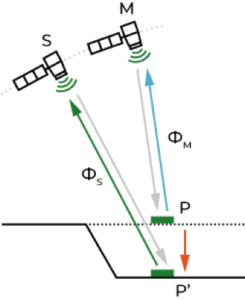
In order to detect a change, InSAR technique exploits the phase difference (ie, interferometric phase) between two acquisitions (called master and image images), which is given by:

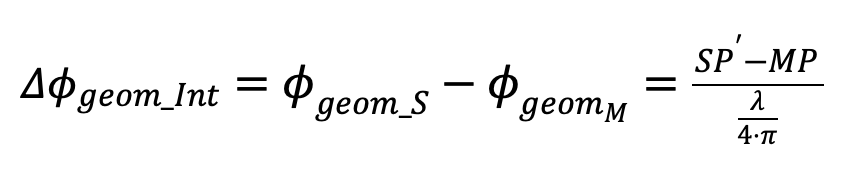
We can separate the component related to the topography and the component related to the displacement   :

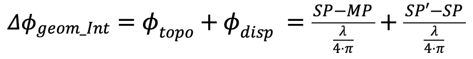
In the equation, we see that the topographic component depends on the relative position of the satellites M and S; Specifically, the bigger is the difference SP-MP the stronger is On the contrary, the displacement component is independent of such positions, allowing measuring the displacements with a millimetric precision. This technique allows monitoring earth’s surface deformation with very high precision, which is very useful in various fields such as mining, monitoring volcanoes, tectonic movements, civil engineering, etc.

The interferometric phase registered by the sensor includes other components such as atmospheric and noise as well as phase ambiguity. To extract the displacement, one needs to estimate the other components and eliminate them.

To filter noise and atmospheric effects on InSAR images, two approaches are used:

Spatial filtering: spatial filtering techniques, such as linear or nonlinear filtering, are applied to remove noise components present in InSAR images. These filters can be based on operations of mean, median, adaptive filtering, wavelet transform, etc. The objective is to reduce the short-scale variations that are generally associated with noise.

Temporal filtering: using a series of InSAR images acquired over a period of time, it is possible to apply temporal filters to remove atmospheric effects. Atmospheric variations tend to occur slowly and can be distinguished from rapid movements of the earth’s surface. Techniques such as difference filtering, temporal polynomial modeling or estimation of atmospheric components can be used to eliminate these variations.

It should be noted that correcting for noise and atmospheric effects can be a complex challenge in InSAR, and different approaches may be required depending on the specific characteristics of the data and the region under study.

Radar data acquisition

A radar system installed on satellites transmits the signal in the microwave range of the spectrum towards the ground surface in an oblique direction (with a look angle), illuminating a surface area with an extension (swath).

A same area is acquired by the satellite in two geometries of acquisition: the ascending one, is acquired when the satellite goes northward and has a side-look from west to east, and the descending one, when it goes southward and has a side-look from east to west.

A SAR sensor can only measure along the Line of Sight (LOS) direction, consequently it can measure only a portion of the real movement (the LOS component). The smaller the angle between the direction of the movement and the LOS, the greater the sensitivity of the technique. The worst case is when the movement is perpendicular to the LOS, when the measured portion of movement is null.

Interferometric synthetic aperture radar

History of development

InSAR Technology

The brief history and the future of the main SAR satellite programmes:

F

First SAR radars were developed back in the 50s. In 1991 the European Space Agency (ESA) launched ERS-1 satellite in 1991 and ERS-2 in 1995 with the first spaceborne satellite sensors, followed by ENVISAT. RADARSAT 1/2 (CSA — Canadian Space Agency) was launched at the same time as well as the high resolution (X-band) COSMO-SkyMed (ASI — Italian Space Agency) and TerraSAR-X (DLR — German Aerospace Center).

The increased availability of satellite data and the funding of international projects, such as TerraFirma and PanGeo, allowed the development of processing techniques including Persistent Scatterer Interferometry (PSI), which first appeared and propagated in the beginning of the 2000s.

Active method commercialisation has started about 10 years ago and still ongoing with more and more practitioners from different industries, mostly mining and oil and gas, but also increasingly construction and civil engineering, adopting the technology for their needs.

New satellite generation is improving the monitoring capability, ensuring regular acquisitions with high temporal frequency and free-for-all data access. Sentinel-1 were launched in 2014 and 2016 to supply the data needs of Europe’s Copernicus programme.

Newly developed and launched private satellite programs, such as Capella Space and Iceye, aim to improve the resolution and shorten the revisit time and start providing data on daily basis. A radar antenna installed on satellites transmits the signal in the microwave range of the spectrum to the ground surface in an oblique line-of-sight direction (with an angle of sight), illuminating a surface with an extension (swath). A same area is acquired by the satellite in two geometries of acquisition: the ascending one, is acquired when the satellite goes northward and has a side-look from west to east, and the descending one, when it goes southward and has a side-look from east to west. A SAR sensor can only measure along the Line of Sight (LOS) direction, consequently it can measure only a portion of the real movement (the LOS component). The smaller the angle between the direction of the movement and the LOS, the greater the sensitivity of the technique. The worst case is when the movement is perpendicular to the LOS, when the measured portion of movement is null.